Rapid prototyping can be a challenge at radio frequencies. Unlike audio or low MHz work, component and interconnect “parasitics” can completely ruin the operation of a circuit operating at VHF and above. At VHF and above (e.g. 30+ MHz), traditional “protoboards” typically have too much capacitance, and jumper wires have too much inductance. Fortunately there are easy solutions as noted below.
RF Prototyping Boards with Ground Planes
One key to solving the parasitics issue is to have a “ground plane” in circuit board designs. The other is to use surface-mount components, and careful, compact layouts. This page shows how we addressed these issues in a university senior design radio circuits course, where we needed to do rapid prototyping.
Here is an example of some of the boards and construction techniques we have used.

These boards have topside pads on a 0.1″ grid and work best with 0805 and 0603 resistors and capacitors, and SOT23 discrete transistors. However, they can support small DIP or SSOP integrated circuits as well, using suitable adapter boards. And of course, once a design is finalized, a full circuit board can be made using free software layout tools such as KiCad and submitted online to be fabricated through vendors such as JLCPCB.


Surface Mount Components
Here is an example of a component assortment I purchased for home use that includes a limited set of such parts as well as adapter boards, tweezers, and small gauge solder and soldering iron tip.


Simple Prototyping
While a full PCB may be the ultimate goal, it is a long process to learn and use the software and websites, and build+shipping times can easily be a week or two. For rapid prototyping, the RF protoboards above with the array of pads and backside ground-plane have been successfully used for years in our courses. One problem was the need to drill holes to make back-side ground-plane connections. A high-power iron with a larger flat tip may also be needed for the backside soldering.
To address that problem, here are some boards I prototyped while making the Radio Design 101 series of videos hosted on YouTube:


Board Fabrication Option 1
These were fabricated through ExpressPCB in the US, which offers a free easy-to-learn layout tool, plus rapid fabrication (a few days) at reasonably low cost (about $60 with shipping in-country). The Standard MiniBoardPlus was used (2.8 x 4 inches with no solder mask).
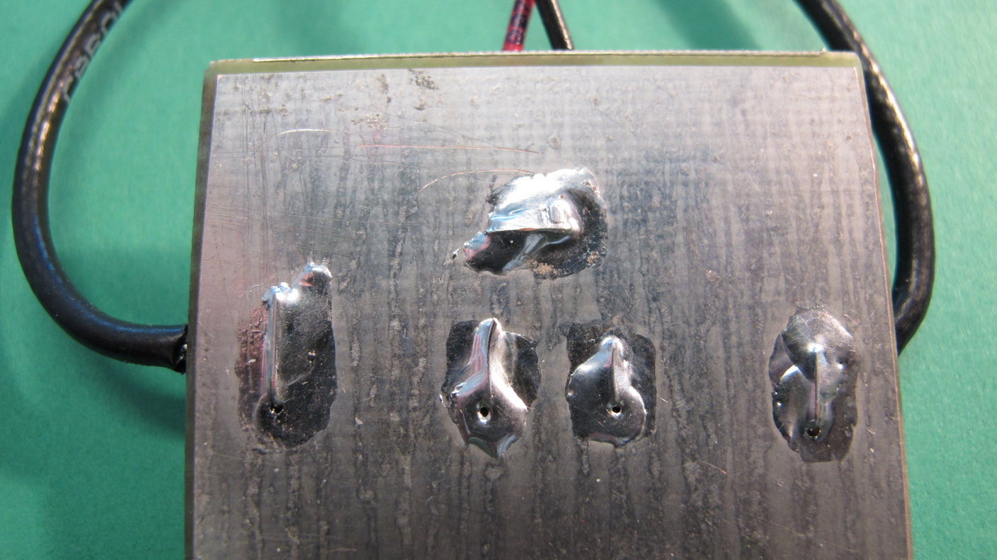
I experimented with several solutions to the via-hole-to-ground problem to avoid the need for drilling. Below is a slide from the mixer section of the Radio Design 101 video series, which used the top-center general-prototyping area of the board.

Note the last bullet in the NOTES section of this slide. While no drilling is required to make a ground-plane connection – just bridge the backside isolated pad to the ground flood – the required solder bridging is a bit tricky due to surface tension. But its a good trade for not requiring a drill !
Option 2: Gerber Files
ExpressPCB uses a proprietary layout file format, since they are a quick one-stop path to getting into PCB design and doing small boards. Most board fab vendors use “Gerber” format files. While I used ExpressPCB, a viewer of the Radio Design 101 series (Maël Hörz) has created a repository on GitHub with Gerber files as well as KiCad source files. Thanks Maël !!
Here is a link to his GitHub page – which has excellent associated descriptions in the “.md” links at the bottom left of the page.
https://github.com/maelh/radio-frequency-prototype-boards

Here’s direct links to these writeups:
Caveats
An important note concerns the IC and the pad-hole sizes on the 0.1″ center protoboards. The hole size was kept small to provide enough pad area on the topside to solder SMD components – but this means some through-hole parts won’t go in. Fortunately the DIP IC leads do 🙂
The other issue is how to use SOP or SSOP type integrated circuits with these boards. This can be done with commercially available adapter boards such as shown here !
